An EV thermal management system is not one problem. It’s eight problems that happen to share coolant.
The battery wants to stay between 15 and 35°C. The power electronics want active cooling at high load. The cabin wants heat in winter and cooling in summer, and it’s competing for the same refrigerant circuit the battery uses. The motor generates heat during aggressive driving. The DC-DC converter has its own overtemperature failure mode. All of these are connected - through coolant loops, refrigerant circuits, and control logic - and all of them interact dynamically.
The work at Mercedes-Benz R&D India was to build this system, component by component, and integrate it into the in-house full-vehicle simulation framework - so that EV and hybrid vehicles (E-Class, S-Class, AMG, EQC) could be simulated with thermally-coupled behaviour from the start of development.
The Framework Context
The in-house simulation framework at MBRD was a MATLAB/Simulink-based full-vehicle model covering drive dynamics, energy consumption, and system behaviour across drive cycles. When the EV programme ramped up, the framework needed to be extended - not patched, extended - to handle the thermal behaviour that ICE vehicles either didn’t have or handled very differently.
Battery thermal behaviour affects range, performance, and aging. Power electronics thermal limits affect peak power availability. HVAC is an energy consumer and a thermal load simultaneously. None of this existed in the framework at the start. Each subsystem had to be modelled, validated, and integrated.
What Was Built
Battery Thermal Model
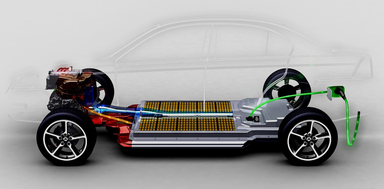
The battery is the most thermally sensitive component in the system. The model covers:
- Heat generation - Joule heating (I²R) from current through internal resistance, plus electrochemical entropic heating. Both depend on SoC, temperature, and C-rate
- Thermal mass distribution - cells, module walls, pack housing, each with appropriate heat capacity
- Cooling path - from cell surface through thermal interface material to cooling plate, then into the coolant loop
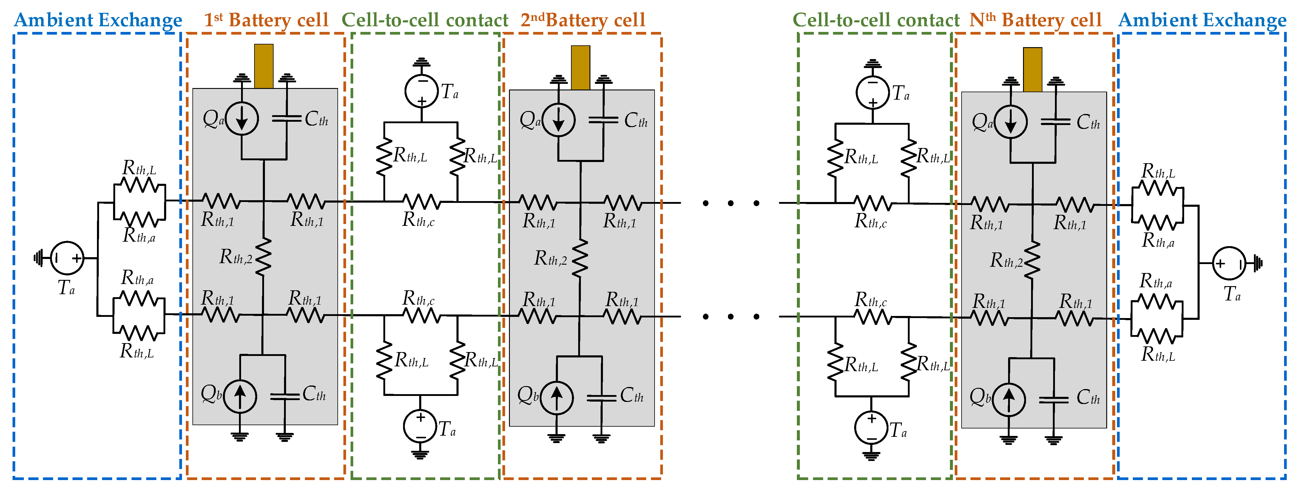
- Cell-to-cell variation - temperature gradients within the pack arise from geometry; corner cells and cells near inlet/outlet see different thermal conditions
The battery thermal model is the one that directly couples to the electrochemical model - temperature affects diffusion rates, open-circuit voltage, and resistance, which affects heat generation, which affects temperature. That loop has to be handled correctly or the simulation drifts.
Current & SoC
     │
     ▼
Heat Generation (I²R + entropic)
     │
     ▼
Cell Thermal Node ──► Cooling Plate ──► Coolant Loop
     │
     ▼
Temperature feedback to electrochemical model
Vehicle-Level TMS Integration
The complete TMS covers battery cooling, power electronics cooling, and HVAC refrigerant circuit - all sharing infrastructure and competing for capacity under peak load conditions.
Power Electronics: Inverter and DC-DC Converter
Both components have thermal models built from physical first principles - thermal resistance networks from junction to case to coolant, with heat generation from switching and conduction losses.
The DC-DC converter model was developed to solve a specific field problem: overtemperature in a particular drive cycle. The model was validated against instrumented test data with 96% accuracy, and the thermal margin was identified before hardware changes were made. This is what a good component model is actually for - not post-processing test results, but answering “what will happen” before the test runs.
Coolant Loop
The hydraulic network connecting the battery, power electronics, and heat exchanger. The model covers:
- Flow distribution - pump characteristic, pipe resistances, parallel branch flow split
- Thermal lag - coolant has mass; a temperature change at the heat exchanger takes time to propagate to the battery inlet
- Control logic - pump speed, valve positions, coolant routing decisions (direct cooling vs. chiller circuit)
Flow distribution matters more than it looks. A pack with nominally uniform cooling can have significant cell-to-cell temperature spread if coolant flow is maldistributed - some cells see higher flow, others see lower. The model has to capture this or it misses the peak temperature location.
HVAC and Refrigerant Circuit
The HVAC system is both a passenger comfort system and a thermal load on the battery cooling circuit. In summer at high ambient temperature, running the cabin at 22°C while fast charging an already-warm battery is a genuine conflict - both want the chiller’s cooling capacity.
The model captures:
- Refrigerant circuit - compressor, condenser, expansion valve, evaporator (vapour-compression cycle)
- Cabin thermal model - solar load, ambient temperature, ventilation, occupant heat load
- Shared chiller - the coupling point between cabin cooling and battery cooling; the control arbitration here directly affects both battery temperature and cabin comfort
Thermal Management Control Logic
Component models alone don’t give you a system. The control logic - when to run the pump at what speed, when to activate the chiller, when to prioritise battery cooling over cabin cooling - determines what the system actually does.
This was implemented in Stateflow: operating mode transitions (normal, fast charge, pre-conditioning, cold start, thermal runaway protection), hysteresis on mode switches, and the priority arbitration when multiple components are competing for cooling capacity.
Integration into the Full-Vehicle Framework
Each subsystem was built and validated independently, then integrated into the framework as a module. Integration exposed the coupling effects that single-component validation can’t catch:
- Cold start - battery is cold, resistance is high, heating is requested; at the same time the cabin is cold, HVAC wants maximum heat; the system has to manage both from a cold state
- DC fast charge at high ambient - battery generates heat from charge current; ambient is already warm; cooling capacity is limited; the interaction between charge rate, ambient temperature, and cooling capacity determines whether the battery stays within its thermal window
- End of a long motorway section entering a city - battery is warm from sustained load; the transition to stop-start driving changes the heat generation profile; the system has to respond correctly or the battery overshoots its temperature target
These transient scenarios are where the integration-level model earns its value. Steady state is manageable. It’s the transitions that break things.
What This Work Feeds Into
The TMS model became the thermal backbone of the full-vehicle simulation framework - used across EV, HEV, and PHEV vehicle configurations (E-Class, S-Class, AMG, EQC). It feeds:
- Range prediction under thermal constraints - real range in hot/cold climates is a thermal problem as much as an energy problem
- Charging strategy optimisation - the fastest charge that doesn’t push battery temperature above the aging threshold requires knowing the thermal system’s capacity
- Battery life prediction - aging models need accurate thermal history; that requires a thermal model that gets the temperatures right across the whole operating envelope
Patterns That Appeared
The failure is always at the interface. Individual component models validate well. The bugs appear at the coupling points - where the battery model hands off temperature to the coolant model, where the HVAC model competes with the battery cooling for chiller capacity. Integration testing is not a validation step. It’s a different class of engineering work.
Thermal systems have memory. A battery pre-conditioned at 25°C and one that started from a cold soak and drove for 30 minutes might be at the same temperature at the 45-minute mark - but they’re in different states. Thermal history affects degradation and performance in ways that a snapshot measurement can’t capture.
Control logic is part of the model. The thermal management system’s behaviour under a given load depends entirely on what the control logic decides to do. A thermally sophisticated hardware design can be undermined by conservative or poorly-arbitrated control. Modelling the physics without the control logic gives you an incomplete picture.