Engine mounts have one job: let the engine move enough to not destroy itself or the chassis, while not letting it move enough to shake the cabin apart. Those two requirements are in direct opposition.
Get it wrong in one direction, and your engine torque reaction cracks the frame. Get it wrong in the other, and the idle vibration transmits straight to the steering wheel and seat. The design space is narrow, the loading is multi-directional, and the rubber changes its behavior depending on temperature, amplitude, and frequency. It’s not a bolt-sizing problem. It’s a dynamics problem.
What You’re Actually Trying to Do
The goal isn’t to eliminate vibration - it’s to keep it out of the frequency range humans are sensitive to. The cabin comfort-critical band is roughly 20–200 Hz. Below 20 Hz, you’re in rigid-body motion territory (ride quality). Above 200 Hz, structure-borne noise dominates.
The engine fires at a frequency that depends on RPM and cylinder count. Four-cylinder at 3000 RPM: 100 Hz firing frequency. You want your mount system to isolate that range. But the mount also has to carry static load (engine weight), handle shock loads (potholes, hard acceleration), and survive 200,000 km.
High stiffness handles static load well. Low stiffness gives better vibration isolation. You can’t have both simultaneously - this is the fundamental constraint.
How the Problem Was Approached
Step 1: Get the mode shapes right.
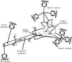
FEA of the powertrain-frame assembly to identify the rigid-body modes of the engine - bounce, roll, pitch, yaw. These are the modes your mount system needs to control. Natural frequency targets for each mode are set by isolation requirements.
Step 2: Parameterize the mounts.
Each mount has stiffness in three translational and three rotational directions. That’s 6 parameters per mount × number of mounts. Not all of them are independently tunable, but it’s still a high-dimensional design space.
Step 3: Optimize.
Objective: minimize Frequency Response Function (FRF) magnitude in the target band at driver seat and steering wheel sensor locations. Constraint: static deflection within limits, fatigue life, packaging.
The optimizer used was a hybrid GA + Nelder-Mead. The genetic algorithm explores the space globally; Nelder-Mead refines the best candidates. This is a pattern that shows up across multiple projects - global heuristic search followed by local refinement. It works.
Damping and Transmissibility
The transmissibility curve is where mount performance lives. Below the resonant frequency, transmissibility is ~1 (force passes through). At resonance, it amplifies. Above resonance, the mount attenuates - and the rate of attenuation depends on damping.
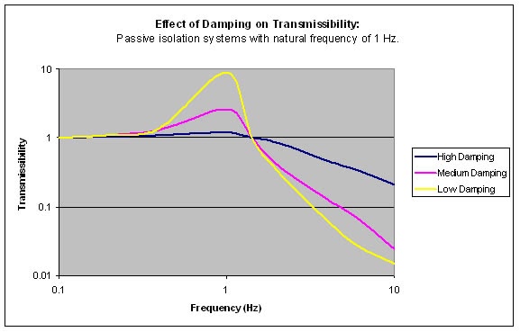
The tradeoff: high damping suppresses the resonance peak but reduces isolation at higher frequencies. Low damping gives excellent high-frequency isolation but leaves a dangerous amplification zone at resonance. Mount design is choosing where to sit on that curve for the specific RPM range and road input spectrum of the application.
The Non-Linearity Nobody Wants to Talk About
Rubber doesn’t behave linearly. Mount stiffness varies with:
- Amplitude - dynamic stiffness at small amplitude is different from large amplitude (higher frequency excitations at small amplitude → apparent stiffer mount)
- Frequency - the storage modulus and loss factor of rubber are frequency-dependent
- Temperature - cold rubber is significantly stiffer (worse isolation), hot rubber softens
Linear models overestimate isolation by ~30% at idle conditions because they use mid-range stiffness values that don’t reflect small-amplitude high-frequency behavior. The fix is to use frequency-dependent complex stiffness - a straightforward extension but requires appropriate test data.
The outcome was a 15–20% reduction in cabin vibration levels, verified on the dynamometer.
Patterns I Keep Seeing
Multi-objective tradeoffs are everywhere. Stiffness vs. isolation, weight vs. fatigue life, performance vs. cost. The optimizer can find Pareto fronts, but the engineer has to decide which tradeoff makes sense for the application. This is not something the algorithm knows.
Validation is where the model earns credibility. Simulation can get you to a good starting point. But real vibration behavior involves joints, preloads, manufacturing variation, and aging - all of which are hard to model precisely. Getting on the dynamometer with an accelerometer and verifying the FRF is what closes the loop.