A battery’s safe operating envelope is not a fixed number. It’s a surface - varying continuously with temperature, state of charge, state of health, and operating history. Getting it wrong in the conservative direction costs performance and range. Getting it wrong in the aggressive direction costs cell life, and at the extreme, safety.
The Current Limits Generator was built to define that surface correctly - from physics, not from conservative blanket rules.
Why This Tool Needed to Exist
At A123 Systems, simulation deliverables for OEM customers include current limits and operating windows as part of pack concept feasibility studies. The question an OEM asks is: given this cell, this pack architecture, and this application duty cycle - what are the charge and discharge current limits across the operating space?
The answer has to account for:
- The cell’s electrochemical constraints (plating onset, side reaction thresholds)
- The cell’s thermal constraints (maximum temperature, maximum temperature rise rate)
- The pack-level system constraints (contactors, fusing, BMS protection thresholds)
- The aging requirement - limits that are safe today but accelerate degradation beyond the target life are not acceptable limits
No off-the-shelf tool did this in a way that integrated all four. The limits were being computed manually, inconsistently, and conservatively. The Configurator was self-initiated to fix that.

The Physics Behind the Limits
Lithium Plating Onset
Lithium plating is the deposition of metallic lithium on the anode surface during charging - instead of intercalation into the graphite. It happens when the anode potential drops to 0V vs. Li/Li⁺, which occurs when:
- Charging current is too high (diffusion limitation in the graphite)
- Temperature is too low (slower diffusion, lower exchange current density)
- SoC is too high (graphite is nearly full, fewer sites available)
Plated lithium is problematic for two reasons: it’s electrochemically inactive (capacity loss), and it can form dendrites that penetrate the separator (safety risk). The charging current limit at any operating point has to stay below the threshold where plating becomes thermodynamically favourable.
The tool computes this threshold as a function of temperature and SoC using the electrochemical model parameters from cell characterisation data.
At any (T, SoC) operating point:

Plating limit = f(anode diffusivity, exchange current density,
                  graphite stoichiometry, electrolyte conductivity)

All of these are temperature and SoC dependent.

Side Reactions
Above a threshold temperature and current, electrolyte decomposition and other parasitic reactions accelerate. These don’t cause immediate failure but consume lithium inventory and electrolyte - the primary mechanism of calendar and cycle aging.
The limits generator includes a side reaction threshold as a function of operating conditions, derived from the cell’s characterisation data and aging test results. The output is not just “safe now” limits but limits consistent with the target cycle life - an aging-aware envelope.
Cell-Level Thermal Limits
Heat generation in a cell is proportional to I²R (Joule heating) plus the electrochemical entropic term. At high current, the cell temperature rises. The rate of temperature rise depends on the thermal resistance to the cooling system and the cell’s heat capacity.
Two thermal limits are relevant:
- Maximum cell temperature - above which aging acceleration becomes unacceptable (typically 45–60°C depending on chemistry and application)
- Maximum temperature rise rate - a constraint on how fast the cell can heat up, relevant for transient high-current events
The tool integrates a simplified thermal model to compute current limits that respect both constraints across all cooling conditions (including worst-case - zero active cooling, as in a cooling system failure).
Thermal Runaway Onset
This is the hard limit. Above a threshold temperature (chemistry-dependent, typically 80–120°C for onset of exothermic reactions), the cell enters a self-heating regime. This limit appears in the current envelope as an absolute ceiling that overrides all other constraints.
The generator includes the thermal runaway onset temperature as a hard boundary, so that any operating window defined by the tool is guaranteed to have margin from this threshold.
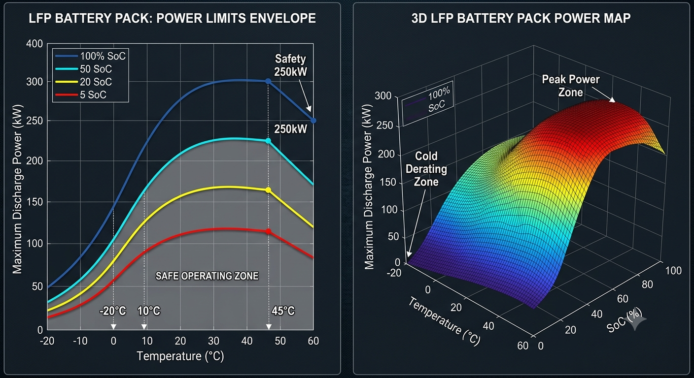
What the Tool Produces
The output is a multi-dimensional current limit map - charge and discharge limits as a function of:
- Cell temperature
- State of charge (SoC)
- State of health (SoH) - limits tighten as the cell ages
- Operating condition (continuous vs. pulse)
This map is directly usable by the BMS as a lookup table, and by the simulation framework as boundary conditions for pack-level simulations.
The tool also generates:
- Operating window visualisation - the safe charge/discharge envelope at each operating point, overlaid with the active constraint (which limit is binding at each point)
- Margin analysis - how far each operating point sits from each constraint boundary
- Aging impact summary - how the envelope contracts as the cell degrades from SoH 100% to end-of-life
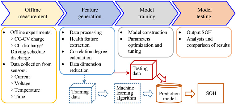
Implementation
Language: Python
Core dependencies: NumPy, SciPy, Matplotlib
Input: Cell characterisation data (HPPC, EIS, capacity tests across temperature), electrochemical model parameters, thermal characterisation, target aging requirement
Output: Current limit tables (CSV/JSON), visualisation plots, summary report
The tool is parameterised - swap in a different cell’s characterisation data and the limits regenerate for that cell. This is intentional: A123 develops multiple cell chemistries and formats, and the OEM customers need limits specific to the cell being evaluated for their application.
Why Self-Initiated
The existing process for defining limits was a combination of cell datasheet values, engineering judgment, and conservative safety margins. It worked - but it left performance on the table, and it wasn’t traceable to the underlying physics in a way that an OEM customer could audit.
The Generator made the physics explicit, made the constraints traceable, and made the output reproducible. It’s been in use since development - which is the test that matters.
Connection to the Broader Simulation Toolchain
The current limits feed directly into:
- Virtual Cell Scaling - scaled cell models need scaled limits
- Pseudo-3D Electro-Thermal Pack Model - pack-level simulations use cell-level limits as boundary conditions
- RFI/RFQ feasibility studies - customer-facing deliverables include the operating envelope as a key output
One self-initiated tool that plugs into three downstream workflows. That’s the return on building infrastructure rather than solving individual instances.